English
  français
  Deutsch
  русский
  español
  português
  العربية
  Melayu
  ไทย
ไทย  Indonesia
  हिंदी
हिंदी 


Energy is the material basis for the survival of life. It is a major problem faced by mankind in the 21st century. Green energy such as wind power, moderate-scale hydraulic power, bioenergy, solar energy, geothermal energy, etc. are increasingly valued by people. Among them, solar energy is the most potential and inexhaustible clean energy. With the development of the photovoltaic industry, its brackets have been transformed from steel products to aluminum alloy profiles, highlighting its environmentally friendly advantages such as lightness, durability, diversified structures, and recyclability. To this end, a reasonable product structure is designed through mechanical analysis, which can not only meet the usage requirements, but also have a simple and lightweight structure.
1.2 Design requirements:
(1) Solar panel specifications: 1650mm×990mm×50mm
(2) Number of solar panels installed: 14 (
3) Solar panel array: 2×7=14
(4) Bracket tilt angle: 30°
(5) Maximum wind speed: 42m/s
(6) Snow load: 0.65kN/m2
(7) Solar panel load: 0.2kN/m2
(8) Installation conditions: Ground, ground roughness category II
(9) Calculation standard: JIS C8955: 2011
(10) Product design life: 20 years
2 Strength design
2.1 Design conditions
①The snow load is 0.65kN/m2, and the maximum wind speed is set to: 42m/s. Seismic loads are not considered. It can be calculated that the vertical snow thickness is less than 1m, which is a calculation for ordinary places.
② According to the above, it can be assumed to be the maximum load in a general place, and the short-term composite load of the fixed load G and the wind pressure load W generated by the storm is used, that is, G+W; the load combination of G+S when there is snow.
③ Calculate the bending strength and bending amount of the material caused by the wind pressure blowing from the front of the bracket (downwind) and the wind pressure blowing from behind the bracket (headwind), and confirm the strength.
④ Maximum height H=2.175m.
2.2 Assumed loads
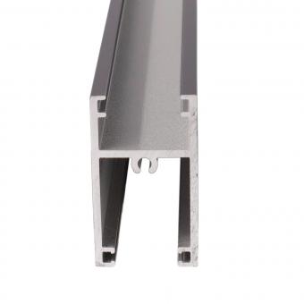
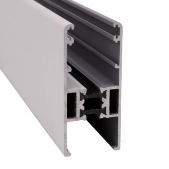
①Fixed load solar module: Gm =0.2kN/m2; Weight of T-shaped track 110: G2= 1.703×9.8/(1.65/2)=0.021kN/m2; Fixed load weight of single T-shaped track 110 G= 0.2+0.021=0.221kN/m2;
②Wind pressure load: Assume that the wind pressure load of the wind blowing from the front of the array (downwind) is Wp Wp=Cw×(0.6×V0 2 ×E×I) Cw—wind coefficient. This scheme is positive pressure. The calculation formula is: 0.65+0.009θ=0.65+0.009×30=0.92 V0—Wind speed 42m/s E—Environmental coefficient, since H=2.175m is less than Zb=5m According to formula (4), the ground roughness category is II Er=1.7×(Zb /ZG)α =1.7×(5/350)0.15=0.8988 E=Er 2 /m2 The wind pressure load of the wind (headwind) blowing from behind the array is Wp, and the wind coefficient is changed to: Cw—wind coefficient. This plan is negative pressure. The calculation formula is: 0.71+0.016θ=0.71+0.016×30=1.19 Wp=1.19×(0.6×422×1.777×1.0)=2.238kN/m2
③Snow pressure load Sp Snow load q: q=0.65kN/m2 Snow area As is the horizontal projected area of the array surface: As=A×cos30°
Slope coefficient Cs=0.84 Sp=Cs×q×As=0.84×0.65×cos30°=0.473kN/m2
④Single T-shaped track load: Load during short-term snow accumulation: G +S =0.221 +0.473 = 0.694kN/m2 Load during short-term storm: G+W=0.221+1.73=1.951 kN/m2 (downwind) G-W=0.221- 2.238=-2.017kN/m2 (upward against the wind) Because the force against the wind is greater than the force along the wind, the following calculations only consider the headwind. Taking the load calculation of the headwind load during a short-term storm, a single T-shaped track q=2.017kN/m2 ×1.65/2=1.664kN/m2
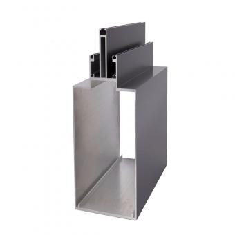
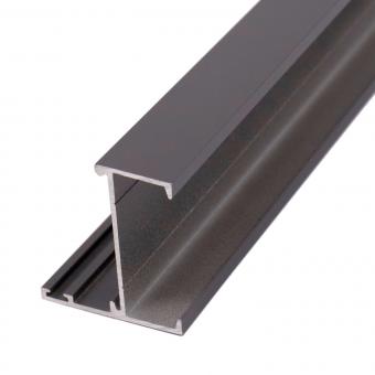
2.3 Stress analysis of square tube
Since the length of the square aluminum 60×1505 is longer than that of the square aluminum 60×600, it is only necessary to check the stability of the square aluminum 60×1505. The force of square aluminum 60×1505 is: F=FB/cos30°=13319.5/ cos30°=15380N. The two ends of the square aluminum 60×1505 are hinged, so μ= 1. From the cross-sectional parameters, I=300653mm4, i=22.1mm; the elastic modulus of aluminum E =6.9×10⁴ MPa. The rod length l = 1505mm. Aluminum alloy σp =175MPa, then the flexibility λ= μl i = 1×1505 22.1 =68 λ1=π E σp =3.14× 6.9×104 175 =62.3. Obtain: λ>λ1 Therefore, the square aluminum 60×1505 is a large compliance rod. Euler's formula is used to calculate Fcr= π2 EI (μl)2 = 3.142 ×6.9×104 ×300653 (1×1505)2 =90303N F=15380N<Fcr, so the overall system is stable.
With the widespread use of aluminum industrial materials and the promotion of environmental protection concepts in the photovoltaic industry, the use of aluminum alloys in its fields has become increasingly prominent, especially in countries such as Europe and Japan. Currently, our company is vigorously developing solar brackets and frame profiles. During the design process, Mechanical analysis of the design section, while ensuring the strength requirements to resist wind pressure and snow pressure, optimize the structure and rational utilization, and design a profile section that is technically feasible, economical in materials, and easy to assemble, to better serve the development needs of the industry.


 IPv6 network supported